For small to medium deployment of Video Over IP , a single Ethernet switch provides adequate number of ports. For example, a Cisco SG350-48MP Network Switch will support up to a combination of 48 Video Over IP Transmitters / Receivers. For larger systems > 48 Video Over IP devices, multiple switches can be connected to scale the system to meet requirement. Two primary methods of connecting multiple Ethernet switches for Video Over IP are : 1) Trunking and 2 ) Stacking.
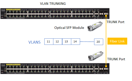
Trunking:
When to use: Video Over IP distribution using VLANs. Multiple VLANs can be used to control Video Over IP switching by managing the VLAN and port assignments.
Why use Trunk: VLANs are local to each switch’s database, and VLAN information is not passed between switches. Creating a TRUNK port allows multiple VLANS to be passed between Ethernet switches. In the example below, 20 VLANS are created and assigned to Trunk port. The Trunk port carries the specified VLAN traffic between the switches. In general, the SFP port in this case the 10Gigabit SFP port is chosen as the Trunk port to provide maximum bandwidth to support the multiple of VLANS traversing across the Trunk Link. If additional bandwidth is needed, a secondary ( or more) port can be added as TRUNK ports.
Switch Management: Each Ethernet switch is still treated independently. Therefore, any configuration/settings of the Ethernet switches need to be performed on each switch separately. For example, each switch CLI/WEB UI will need to be accessed via separate IP address.
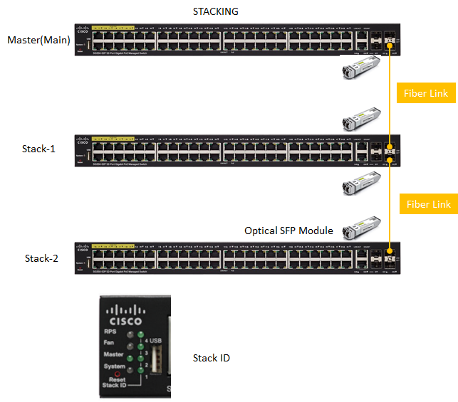
Stacking:
When to use: Video Over IP solutions such as the Octava PRO DSX that supports Layer 3 IGMP Multi Cast Management Protocol in general should use Stacking when > 48 devices are needed.
Why Use Stacking:
Stacking switches have the ability to be connected together and operate together as a single unit. Stacking allows users to expand the network capacity without the hassle of managing multiple devices. Stackable switches can be added or removed from a stack as needed without affecting the overall performance of the stack.
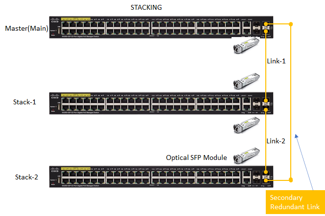
Benefit of Stacking switch topology include:
-Stackable switches can be added or removed from a stack as needed without affecting the overall performance of the stack.
– A ‘ring’ topology can be created by adding a secondary Fiber link. The Secondary Fiber link can provide a redundant path between the switches in the stack. In the event that any 1 link is disrupted/fails, the stack can continue to transfer data between the stack.
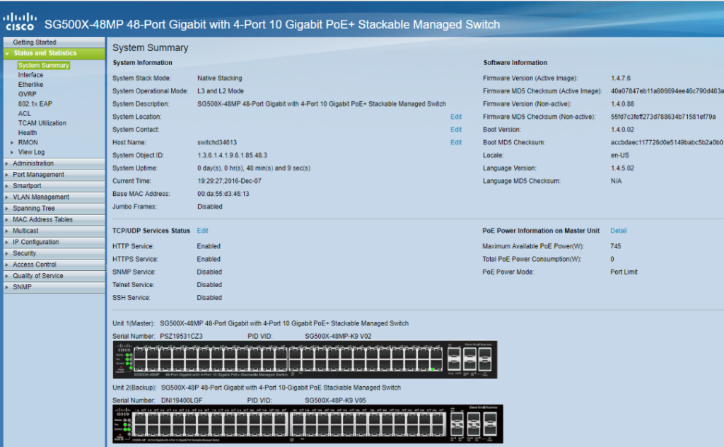
Switch Management: All switches in the STACK are treated as 1 single aggreagate switch. Therefore any configuration / settings only need to be managed as 1 single switch.
A 2 switch Stack system is shown below. It can be seen that in the switch management console, the 2 switches in the stack can be accessed , managed as 1 single switch . Thus eliminating the hassles of having to manage each switch separately.
Switches that support Stacking:
Model
Stacking Support
SFP Link Port
Cisco SG350X
4 switches max
10 Gigabit
Cisco SG550X
8 switches max
10 Gigabit